- A complete tube sheet drawing has five parts: title block, front view, section view, hole table and notes.
- The reference hole and revision are what make a hole pattern machinable and traceable.
- Hole tolerance is read as a band; tighter TEMA classes narrow it, and notes often allow a few over-tolerance holes.
- Grooves, pass partition grooves and gasket face finish are the details most often missing from RFQ drawings.
- Ten checks before sending a drawing remove most of the questions that delay a quote.
What's on a tube sheet drawing
Every tube sheet (or tube plate, as UK drawings call it) is defined by the same few views, even when fabricators lay them out differently. Here is a sample with the important features numbered.
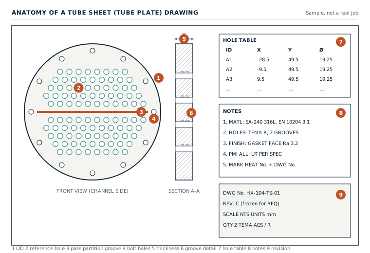
| # | Feature | What to check |
|---|---|---|
| 1 | Outside diameter | Finished OD and tolerance; whether the edge is welded (fixed) or gasketed |
| 2 | Reference hole | One hole dimensioned from the centre; everything else is located from it |
| 3 | Pass partition groove | Width, depth and layout must match the channel pass plates |
| 4 | Bolt holes | Count, diameter and pitch circle (PCD) for gasketed tube plates |
| 5 | Thickness | Finished thickness, after facing and any clad allowance |
| 6 | Groove detail | Groove count, width, depth and position in each tube hole |
| 7 | Hole table | Coordinates and diameters, or a pitch-and-pattern note |
| 8 | Notes | Material, certificates, finish, NDT, marking |
| 9 | Revision | The revision you send is the one we quote; changes after that cost time |
Title block and revision
Start in the corner. The title block gives the drawing number, revision, units, scale and quantity, and often the TEMA type and class (for example AES / R). Freeze the revision before you send an RFQ. If a later revision changes the hole pattern, the CNC program, material cut and inspection plan all change with it.
Check the units too. US drawings are usually in inches with tube sizes in BWG gauge; European and Indian drawings are metric. Mixed units on one sheet are common on export jobs and fine, as long as each dimension says which it is.
Front view: the hole pattern
The front view is the tube plate seen from the channel side. It shows the hole pattern, the reference hole, pass partition grooves, bolt holes and tie rod holes. Hole positions are given one of two ways:
- Hole table: every hole listed with X and Y coordinates from the centre. Unambiguous and easy to program, but long.
- Pitch and pattern: tube OD, pitch, layout angle and one reference hole, plus the outer tube limit. Compact, but every missing piece is a question.
Either works. If you use a pitch note, make sure it states the layout angle (30°, 60°, 90° or 45°) and where the pattern starts. Our tube count and layout guide explains how pitch, pattern and pass lanes decide the hole count.
Section view: thickness, grooves and faces
The section cuts through the tube plate to show what the front view can't: finished thickness, groove detail inside each hole, gasket face finish, any weld preparation at the edge, and cladding if there is any.
- Grooves matter for expanded joints. Most drawings call for one or two grooves per hole; the width and depth must suit your rolling procedure. See tube hole design for roller expansion.
- Weld preparation appears on fixed tube sheets that are welded to the shell, and on holes prepared for tube-to-tubesheet welding.
- Clad layer thickness should be stated as the minimum after machining, because facing and grooving remove some of it. See clad tube sheets.
Reading the tolerances
Tube hole tolerance is easiest to read as a band: a lower limit just above the tube OD and an upper limit beyond which the joint won't seal reliably.
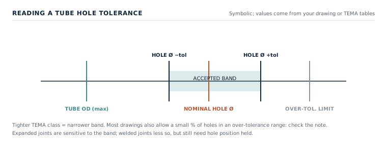
TEMA class R, C or B sets standard hole diameters and tolerances for each tube size; many drawings simply reference them. Notes often allow a small percentage of holes in a slightly larger over-tolerance range. Hole position tolerance, ligament minimums and perpendicularity on thick plates are separate requirements. For the detail, see tube sheet tolerances explained and our TEMA tolerance reference.
The notes block
Notes carry the requirements that don't fit a dimension line. A good set covers:
- Material specification and grade, e.g. SA-240 316L or EN 1.4404, and product form (plate, forging, clad)
- Certificate type, e.g. EN 10204 3.1, or 3.2 with a named inspector
- TEMA class and hole tolerance reference
- Surface finish on gasket faces (Ra)
- NDT and PMI requirements: UT of the plate or forging, PMI on alloys
- Marking: heat number and drawing number, and where on the plate
Metric, imperial and BWG on the same drawing
Export drawings often mix systems. A US datasheet will give tube size as ¾ in OD, 16 BWG; a European one as 19.05 × 1.65 mm. They describe the same tube. What matters on the tube plate drawing is that the hole diameter and tolerance are stated in one unit and that the pitch is not rounded during conversion: 15/16 in is 23.8125 mm, and rounding to 24 mm over 40 pitches moves the last hole almost 7.5 mm.
| Tube OD | Common pitch (30°) | Common pitch (90°) | Typical gauge |
|---|---|---|---|
| 15.88 mm (5/8 in) | 20.64 mm (13/16 in) | 20.64 mm | 16–18 BWG |
| 19.05 mm (3/4 in) | 23.81 mm (15/16 in) | 25.40 mm (1 in) | 14–16 BWG |
| 25.40 mm (1 in) | 31.75 mm (1¼ in) | 31.75 mm | 12–14 BWG |
| 31.75 mm (1¼ in) | 39.69 mm (1 9/16 in) | 39.69 mm | 12–14 BWG |
Red flags worth a second look
- A hole table whose total doesn't match the tube count in the title block or datasheet.
- Pitch given without the layout angle, or an angle given without the direction of shell-side flow.
- Clad tube plates with only the as-bonded clad thickness stated.
- Two tube sheets for the same exchanger drawn at different revisions.
- A material grade with no product form (plate or forging) or no certificate type.
- Tolerances quoted from a TEMA class that differs from the one in the title block.
None of these stop a job, but each one is cheaper to fix on paper than after the first hole is drilled.
Ten checks before you send it for a quote
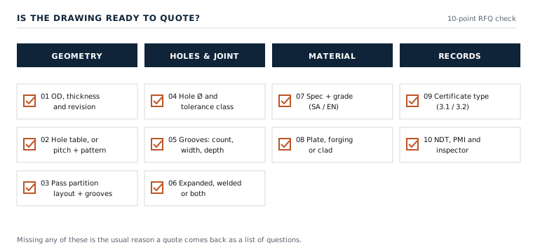
Most delayed quotes come down to a missing groove detail, an unstated certificate type or a pitch note without a reference hole. Our posts on tube sheet RFQ mistakes and ten questions before your first order cover the commercial side.
What happens after you send it
When a drawing reaches us, we check it can be machined: ligament width at your pitch and thickness, deep-hole drilling accuracy, groove tooling and pass partition layout. Questions go back in one list, not one at a time. Once the revision is confirmed, the hole table becomes the CNC drilling program, and the inspection report is written against the same drawing number and revision. That's the CNC tube sheet drilling service in practice.
Frequently asked questions
A list of every tube hole with its X and Y coordinates from the centre (or a reference point) and its diameter. It removes any doubt about hole positions and translates directly into a CNC drilling program.
One hole dimensioned directly from the tube sheet centre. When the drawing uses a pitch-and-pattern note instead of a hole table, every other hole is located from it.
Either from the drawing itself or from the TEMA tables for the stated class (R, C or B) and tube size. Notes may allow a small percentage of holes in an over-tolerance range.
No. Tube plate is the British and Australian name; the drawing shows the same views, holes and notes.
Groove dimensions, the certificate type, the pass partition groove details, and a reference hole or layout angle when no hole table is given.
Sources and further reading
- TEMA, Standards of the Tubular Exchanger Manufacturers Association, tube hole diameters and tolerances
- ASME BPVC Section VIII Division 1, Part UHX (tubesheet design)
- EN 10204, metallic products: types of inspection documents