What a tube sheet does in a shell-and-tube heat exchanger
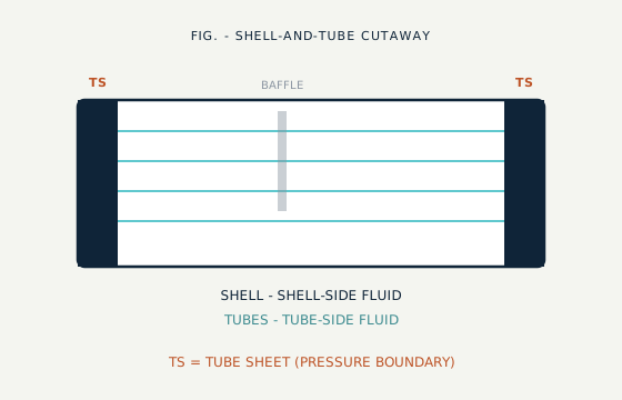
Every shell-and-tube exchanger has two fluids that must not mix. The tube sheet separates them, locates the tubes, and carries pressure and thermal load across the perforated ligament field.
In a shell-and-tube heat exchanger, boiler, or condenser, one fluid flows inside a bundle of tubes and a second fluid flows around those tubes inside the shell. The tube sheet is the component that separates the two circuits: a thick circular (occasionally rectangular) plate or forging, drilled with a precise hole pattern, into which every tube end is expanded, welded, or both.
Two requirements apply at once. First, the sheet must remain a reliable pressure boundary under differential pressure and thermal cycling without unacceptable bowing or joint leakage. Second, every hole must support a durable tube-to-tubesheet joint through vibration, corrosion, and — depending on service — aggressive fluids on one or both faces.
That combination is why tube-sheet design is its own discipline. Thickness, hole pattern, material, and joint method are selected together under codes such as TEMA and ASME Section VIII, then verified against the project fluids, pressures, and temperatures before drilling starts.
Shell-side flow direction is shaped by baffles between the sheets — baffles are not pressure-boundary tube sheets. See baffled tube sheets for that distinction. For application-focused product pages, continue to heat exchanger tube sheets. For forged blank form, see forged tube sheets.
The five things that define a tube sheet
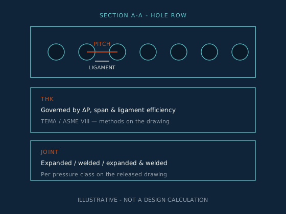
These are the variables that usually appear on a drawing — diameter, thickness, hole size, pitch/pattern, and ligament — plus the joint method that closes each hole.
- 01 · OD
Sheet diameter (OD)
Set by shell diameter and tube count; drives blank size and machining envelope required.
- 02 · THK
Thickness
Calculated from differential pressure, unsupported span, material allowable stress, and ligament efficiency per ASME/TEMA methods — not a rule-of-thumb gauge.
- 03 · HOLE
Hole diameter
Matched to tube OD and joint method (expanded, welded, or both). Controls fit-up and leak path risk.
- 04 · PITCH
Pitch & pattern
Triangular (30°/60°) for tube density; square (90°/45°) when mechanical cleaning lanes are required.
- 05 · LIG
Ligament
Remaining metal between adjacent holes — the strength-bearing cross-section the thickness calculation checks against.
- Pitch
- Centre-to-centre distance between adjacent tube holes.
- Ligament
- Metal left between holes; drives local strength and minimum thickness checks. See ligament efficiency.
- Tube-to-tubesheet joint
- How the tube is sealed in the hole — expanded, welded, or both. See expanded vs welded.
- Pass partition groove
- Channel-side groove that separates passes; a machining feature, not a structural family. See machining features.
Tube sheet types compared
Choose the structural family first — it decides how the exchanger handles thermal expansion — then material and thickness. This hub explains the differences; spoke pages carry product detail.
Comparison table — swipe or scroll horizontally · first column stays pinned
| Type | How it works | Thermal expansion | Cleanability | Typical use | NPRO page |
|---|---|---|---|---|---|
| Fixed tube sheet | Both sheets welded to the shell | Shell expansion joint, or none if ΔT is low | Shell-side hard to clean mechanically | Low-cost, clean services | Fixed tube sheets |
| Floating tube sheet | One end free to move inside the shell | Free axial movement of floating head | Bundle can be withdrawn for cleaning | High ΔT, fouling services | Floating tube sheets |
| U-tube | Single sheet; tubes bend and return | Each tube expands independently | Tube-side cleaning limited by U-bends | High pressure / temperature | U-tube tube sheets · U-tube vs straight |
| Double tube sheet | Two sheets create a leak-detection gap | Follows base exchanger type | Design-specific | Toxic or high-purity duties where cross-contamination is critical | Double tube sheets |
| Clad tube sheet | Base metal with corrosion-resistant face | Follows fixed / floating / U-tube base | Follows base design | Aggressive fluid on one face, cost-sensitive base | Clad vs solid |
| Condenser / boiler duty | Application labels on any structural type | Per structural type | Per service | Power, process condensation, boiler exchangers | Boiler vs HEX · HEX tube sheets |
| Forged vs rolled plate | Blank form before drilling | Independent of structural type | N/A | Large / high-pressure blanks often forged | Forged tube sheets · Forged vs rolled |
| Baffled / segmental features | Shell-side flow features near the sheet | Design-specific | Affects shell-side access | Large exchangers needing flow control | Baffled tube sheets |
Materials vs service
Thickness and pitch come from pressure and temperature. Material is chosen for compatibility with the fluids on each face — often two different environments. Use the grade pages and selection guide below; do not treat this table as a substitute for a project corrosion review.
Materials table — swipe or scroll horizontally · family column stays pinned
| Material family | Grades (linked) | Typical service | Watch-outs |
|---|---|---|---|
| Stainless (austenitic) | SS304, SS316L, SS321, SS347 | Chemical, utility, many process duties | Chlorides, crevice corrosion, sensitization at welds |
| Duplex / super duplex | Duplex 2205, Super Duplex 2507 · Duplex family | Chloride-bearing waters, higher strength | Fabrication procedure control; see duplex vs 316L |
| Nickel alloys (Inconel / Monel) | 600, 625, 718; Monel 400, K500 · Nickel / Monel | High temperature, severe corrosion | Cost, weld procedure, galvanic couples |
| Hastelloy | C276, C22 · Hastelloy family | Aggressive acids / chemical process | Specify grade carefully; do not interchange C-family casually |
| Titanium | Grade 2, Grade 5 · Titanium | Seawater / chloride-rich cooling | Fabrication practice; solid vs clad decision |
| Copper-nickel (context) | Cu-Ni & Inconel 625 article | Marine condensers, desalination context | Confirm grade page availability in RFQ; see also marine-grade stainless limits |
Deeper reading: tube sheet material selection, grade equivalence resource, and standards hub.
ASME Section VIII, TEMA, and material specs
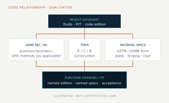
Codes set the calculation and construction framework. They do not replace the project datasheet, and mentioning a code here is not a claim that every order is certified under that stamp.
ASME Section VIII (Division 1, with tubesheet design methods commonly referenced under UHX for many shell-and-tube designs) governs pressure-boundary design when ASME is the project code. Final thickness and ligament checks belong to the responsible design engineer using the applicable edition.
TEMA classes R, C, and B describe mechanical construction practice for tubular exchangers. Tolerance and layout context: TEMA classes explained and TEMA tolerance resource. Always confirm against the edition named on the drawing.
Material product forms are typically called out with ASTM/ASME specs (for example SA-516 plate, SA-240 stainless plate, or forging specs such as SA-182 / SA-266 / SA-965 where applicable). These are generic examples — the purchase order must name the actual spec. NPRO states ISO 9001 QMS and mill-test / NDT documentation practices on the About page; project-specific PED/CE or stamp requirements are confirmed during enquiry.
Continue at the standards hub.
Tube-hole drilling, pitch layout and tolerances
This section targets practical queries such as tube sheet layout and tubesheet ligament — without inventing a universal tolerance table.
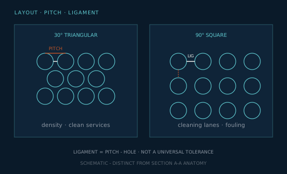
Triangular vs square pitch. Triangular pitch packs more tubes into a given diameter and is common for clean services. Square pitch leaves straight cleaning lanes when the shell-side fluid fouls. Layout planning context: pitch layout resource.
Ligament. Ligament width is pitch minus hole diameter (geometry), while ligament efficiency enters strength calculations. Short ligaments raise thickness and drilling risk. See ligament efficiency.
Hole tolerances. Thickness, flatness, hole position, hole diameter, and perpendicularity are separate families — they are not one ± value. Read them from the drawing and ITP; see tube sheet tolerances explained.
Joints. Expanded, welded, or expanded-and-welded joints follow pressure class, fluid hazard, and code notes — expanded vs welded.
CNC drilling. Pattern execution, feature machining, and drawing-led RFQs: CNC tube sheet drilling and CNC drilling article.
Have a hole table or DXF ready? Send the drawing for a manufacturability review before you freeze the PO.
What drives tube sheet thickness
Thickness is calculated for the design — not picked from a catalogue gauge. Drivers sit between layout (Ch. 06) and release verification (Ch. 08).
Final thickness comes from the applicable ASME UHX / TEMA calculation path for the design. Drivers typically include:
- Design pressure and temperature (differential across the sheet)
- Material allowable stress at design temperature
- Unsupported diameter / span and support conditions
- Tube layout and ligament efficiency
- Corrosion allowance and cladding (if any)
Walkthrough: how tube sheet thickness is determined. NPRO reviews drawing thickness against manufacturability during enquiry — we do not invent a substitute design calculation on this page.
What buyers usually verify before release
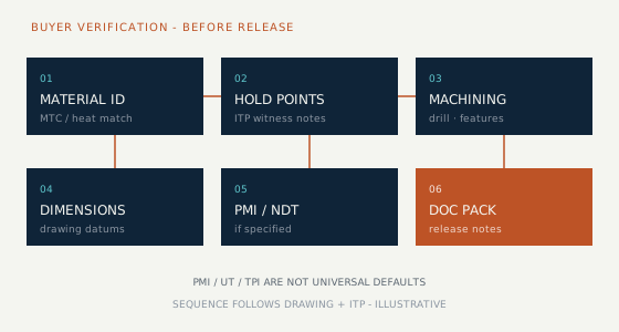
A coherent QA sequence follows production. PMI and NDT apply only where the drawing or ITP requires them — not as universal defaults.
Typical order: material identity → manufacturing hold points → machining/drilling → dimensional inspection → any PMI/NDT required by the drawing or ITP → documentation pack. Guide: tube sheet inspection & testing.
About NPRO documentation practices: mill test certification and NDT partner network are listed on About — certifications. Whether a given order includes EN 10204 type 3.1 certificates, bond UT, or third-party inspection release notes is confirmed against the purchase order and ITP during enquiry — not assumed from this guide.
In-service damage context: damaged tube sheet holes and warning signs.
What to send for a tube sheet quote
Incomplete RFQs produce non-comparable quotes. Use this checklist, then the buyers guide and RFQ articles.
RFQ checklist — swipe on narrow screens · step number stays pinned
| # | RFQ field | Why it matters |
|---|---|---|
| 1 | Drawing (PDF / DWG / STEP) or dimensional envelope | Hole table, grooves, faces, datums |
| 2 | Material grade + product-form spec | Plate vs forging; solid vs clad |
| 3 | OD & thickness (or design inputs if thickness TBD) | Blank size and machining envelope |
| 4 | Hole diameter / quantity / pitch / pattern | Drilling time and ligament risk |
| 5 | Tolerance class / TEMA class / code edition | Acceptance criteria |
| 6 | Grooves, cladding, special features | Extra ops and NDT scope |
| 7 | Quantity and delivery location / date | Scheduling and packing |
| 8 | Inspection / TPI and document pack | MTC type, PMI, UT, release notes |
Helpers: buyers guide, RFQ mistakes, ten questions before you order, lead times, how to read a tube sheet drawing.
Ready to enquire? Use the form, WhatsApp, or email — include the checklist fields above.
CNC drilling & manufacturer path in India
When you are ready to source or machine a tube sheet, these pages cover manufacturer capability, CNC drilling, and how to start an engineering review:
Questions engineers actually ask
A tube sheet is the thick perforated plate or forging that holds each tube end and forms the pressure boundary between the tube-side and shell-side fluids in a shell-and-tube heat exchanger, boiler, or condenser.
A tube sheet is a pressure-boundary component that seals the two fluid circuits and anchors tube ends. A baffle sits inside the shell between tube sheets, is not a pressure boundary, and directs shell-side flow while supporting the tubes. See baffled tube sheets for feature context.
Fixed designs suit low differential temperature and clean shell-side services. Floating heads handle higher thermal expansion and allow bundle withdrawal for cleaning. U-tube designs use one sheet and let tubes expand independently — common in high pressure/temperature service. Compare U-tube vs straight-tube guidance on the blog.
There is no single “best” grade. Seawater and chloride-rich cooling often drive titanium, copper-nickel, duplex/super duplex, or suitably clad constructions — after a project-specific corrosion and galvanic review. Start with the material selection guide and marine-grade notes; confirm against the datasheet.
Thickness is calculated from design pressure/temperature, unsupported span, ligament efficiency, and material allowable stress using the applicable ASME Section VIII / TEMA methods for the design. It is not a standard gauge chosen from a chart. See the thickness article for the buyer-facing walkthrough.
Pitch is the centre-to-centre distance between holes. Ligament is the metal remaining between holes. Ligament efficiency feeds strength calculations and is one reason dense patterns need careful thickness and drilling control.
Hole diameter, hole position, perpendicularity, thickness, and flatness are separate tolerance families. Contractual values live on the released drawing, cited standard edition, and ITP — not on a generic web table. See tube sheet tolerances explained.
A drawing or dimensional envelope, material grade and product-form spec, OD/thickness, hole diameter/qty/pitch/pattern, code/TEMA class, special features, quantity, destination, and inspection/document requirements. Use the RFQ checklist on this page and the buyers guide.
Go deeper — types, materials, tools and guides
Types
Materials
Tools & guides