NPRO Journal · ENGINEERING
Tube Sheet Tolerances
Explained
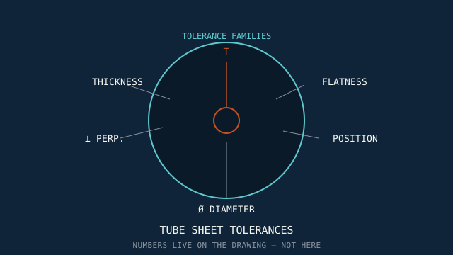
Thickness, flatness, hole position, diameter and perpendicularity — what each family controls, and why the drawing still owns the numbers.
Thickness, flatness, hole position, diameter and perpendicularity — what each family controls, and why the drawing still owns the numbers.
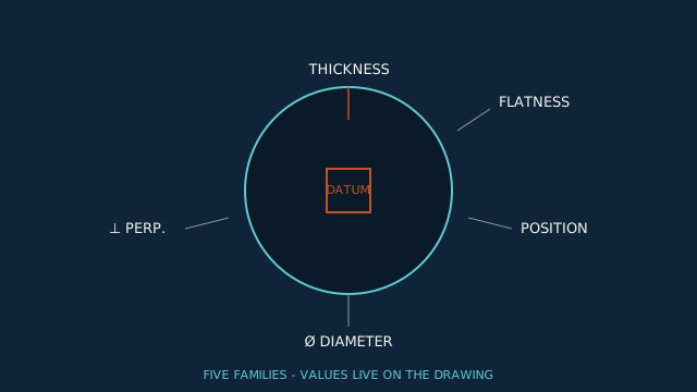
Tube sheet tolerances are not a single number on a title block. They are a family of controls — thickness, flatness, hole position, hole diameter, and perpendicularity — each protecting a different assembly or strength outcome. Buyers who ask only “what tolerance do you hold?” without naming which characteristic often receive answers that cannot be compared across vendors.
This guide explains what each tolerance family means in tube-sheet practice and how it should appear on drawings and inspection plans. It does not publish universal numeric tables. Contractual values live on the released drawing, the governing standard edition cited by the project, and the inspection and test plan (ITP). Use TEMA tolerance reference as planning context when TEMA is cited — always confirm against your revision. For how features and datums interact in manufacture, see CNC tube sheet drilling. For the buyer-facing overview of types, materials and layout terms, see the tube sheet guide.
Vendors and inspectors use different tools for different characteristics: micrometers or UT thickness gauges for thickness; straightedges, dial indicators, or CMM for flatness; coordinate measuring or optical systems for hole position; bore gauges or pin gauges for diameter; specialised setups for perpendicularity. Collapsing all of that into “±0.1 mm” in an email guarantees dispute. The drawing’s tolerance block, GD&T frames, and general notes assign the real limits.
Procurement should also separate manufacturing capability talk from contractual acceptance. A shop may routinely hold tight hole diameter on small patterns and still need a different strategy on a 2,000-hole condenser sheet. Capability statements are enquiry-specific; acceptance is revision-specific. That distinction keeps RFQs honest and aligns with how complete drawings and RFQ fields — see RFQ mistakes that delay quotes — feed manufacture.
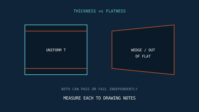
Thickness tolerance bounds how far finished thickness may vary from the nominal after facing. It protects design minimum thickness, cladding minimums on clad constructions, and consistent tube projection. Measurement is typically multi-point across the diameter — a single centre reading can miss wedge.
Practical notes:
Do not substitute a mill plate tolerance for a finished tube-sheet thickness tolerance unless the drawing says so.
Flatness limits deviation of a face from a plane. Gasket lands and channel/shell mating faces are the usual concern: a wavy face concentrates bolt load and invites leaks even when average thickness is acceptable. Flatness and thickness can pass or fail independently — a plate can be thick enough yet out of flat, or flat yet under minimum thickness at a local low spot.
Inspection methods range from straightedge and feeler gauges to CMM sampling on large diameters. The drawing or ITP should state the method when flatness is contractual. Protect accepted faces during later drilling setups; re-clamping can introduce new distortion that needs re-check.
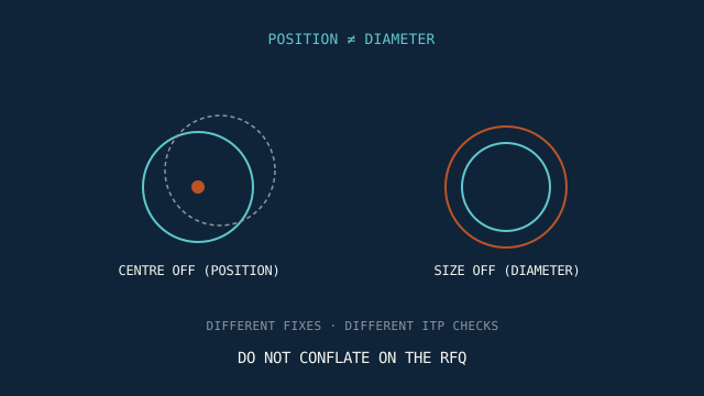
Positional tolerance controls where hole centres land relative to datums and to each other (pitch accuracy). Position errors stack into ligament shortfalls, baffle misalignment, and tube-bundle assembly problems. Pattern type — triangular or square — changes which directions matter most; see how tube sheet thickness is determined for the ligament/strength relationship and pitch layout for layout context.
Position is not diameter. A hole can be the correct size and still be in the wrong place. CNC programmes and inspection reports should treat them as separate characteristics. Deep drilling and thermal growth during machining are process risks discussed in the CNC drilling guide — this article stays on the tolerance meaning, not the drilling process.
Diameter tolerance sets acceptable finished bore size for expansion, strength weld, or hybrid joints as designed. Undersize bores resist tube insertion or expansion; oversize bores can undermine joint strength or leak paths. Finish and burr condition often sit beside diameter on the ITP even when not named “tolerance.”
Joint method on the drawing drives the diameter strategy — expanded vs welded joints are covered in expanded vs welded. Never assume hole diameter equals tube OD without reading the note.
Perpendicularity (and related orientation controls) limits how much the hole axis may tilt relative to a datum face. Tilt affects expander alignment, weld prep geometry, and local ligament loading. Not every drawing calls perpendicularity out explicitly; when it does, inspection must use the same datum as manufacturing.
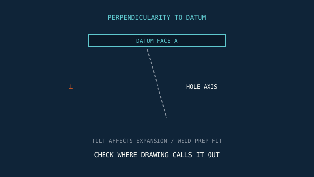
Related orientation controls (parallelism between faces, coaxiality of counterbores) appear on feature-heavy sheets. Treat each symbol as a separate requirement — see machining features for counterbore and face context.
Tolerances stack. A hole that is near the large end of diameter tolerance and near the edge of position tolerance can leave less ligament than a casual reader expects — the educational ligament width ≈ pitch − diameter relationship still depends on where the centre actually landed. Flatness error on a gasket face can open a leak path even when every hole meets diameter. Perpendicularity error can make an expander follow a tilted axis and ovalise the entrance over repeated retubes.
Designers choose limits knowing those interactions; shops should not “spend” the entire tolerance budget on every characteristic simultaneously without understanding the stack. When a repair or deviation is proposed, re-check interactions rather than approving one gauge reading in isolation — especially on damaged bores discussed in damaged tube sheet holes.
These practices mirror the documentation discipline summarised on testing & quality without rewriting a full QA sequence here.
Tolerances only make sense relative to datums — usually a primary face, centre, or bolt circle. If the RFQ omits datum language that exists on the drawing, vendors may assume different setups. TEMA-oriented projects may reference class-appropriate practice for tube holes and related dimensions; TEMA class itself is not a quality tier — see TEMA R vs C vs B. Numeric TEMA values, when used, must match the current edition cited by the contract; this article will not invent a substitute table.
Tolerance families — swipe on narrow screens · family column stays pinned
| Family | Protects | Typical confusion |
|---|---|---|
| Thickness | Min metal / clad | Mill plate tol ≠ finished tol |
| Flatness | Seal / bolt load | Confused with thickness |
| Position | Pitch / ligament | Confused with diameter |
| Diameter | Joint fit | Assumed = tube OD |
| Perpendicularity | Axis tilt | Ignored if not measured |
Scenario 1 — Condenser with 1,500+ holes: Positional tolerance and pitch verification dominate risk. Diameter still matters for joint fit, but a beautiful diameter report with drifted centres will not assemble cleanly. Budget inspection time for pattern audits, not only bore gauges.
Scenario 2 — Multi-pass process exchanger: Flatness on gasket lands and groove depth tolerances sit beside hole controls. A leak at the channel pass partition is often a feature problem, not a hole-diameter problem.
Scenario 3 — Thick forged high-pressure sheet: Thickness variation and face parallelism after heavy facing cuts matter for gasket load and tube projection. Confirm multi-point thickness maps on the ITP. Blank-route context: forged vs rolled plate tube sheets.
In every scenario, paste the drawing’s numbers into the RFQ only if they match the revision character-for-character — otherwise reference the revision and attach the PDF.
Pass-partition groove depth/width, gasket-land finish, counterbore depth, and bolt-circle position are tolerance families of their own. A sheet can meet tube-hole diameter and still fail assembly if groove depth is shallow for the partition plate. Treat feature controls as first-class citizens on the RFQ — CNC tube sheet drilling covers how those geometries are executed; this article insists they carry explicit limits on the drawing rather than shop folklore.
Surface finish symbols (Ra/Rz) need measurement method notes when they are contractual. “Machined finish” without a number may be intentional; do not invent an Ra and then reject the vendor against your invention.
Commonly thickness, flatness, hole position, hole diameter, and perpendicularity (plus feature-specific limits). Exact values come from the drawing and cited standards — not from a universal shop default.
Only when the project cites TEMA (or another standard) as governing. Always use the edition named in the contract.
No. Thickness is about metal depth; flatness is about face planarity. Both can matter for sealing.
Yes. Diameter and position are separate characteristics with different inspection methods and corrective actions.
Best practice is to reference the drawing revision. If you paste numbers, they must match that revision exactly.
Only where the drawing or ITP requires it. When required, measure to the named datum.
Share the dimensional and GD&T notes with your enquiry so inspection scope matches the same revision.
Send an Enquiry →