NPRO Journal · MAINTENANCE
Damaged Tube Sheet
Holes
Causes, engineered repair options, and when re-machining may be possible — after measurement and design review, not improvisation.
Causes, engineered repair options, and when re-machining may be possible — after measurement and design review, not improvisation.
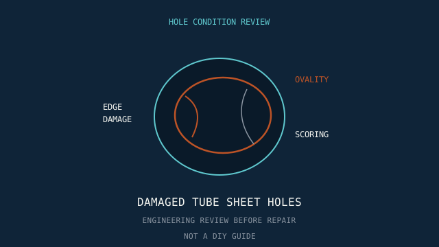
Damaged tube sheet holes show up as ovality, scoring, bell-mouthing, corrosion pits, cracked ligaments, or deformed lands after tube pulls. The wrong response — blending past remaining ligament, welding without procedure, or “opening up” a bore to fit the next tube — can turn a local defect into a pressure-boundary failure. The right response starts with mapping, engineering review, and a repair path that the design and Code package allow.
This article covers common causes, repair option classes, and when re-machining may be possible. It is not a do-it-yourself repair manual and does not authorise field repairs without responsible engineering review. For early leak and corrosion patterns that precede hole damage, see warning signs before a tube sheet fails. For new-build acceptance and quality context, see testing & quality — a different problem from in-service damage.
During a forced leak or planned turnaround, teams feel pressure to “open the hole and retube tonight.” Pause long enough to capture as-found condition. Once grinding or welding starts, the forensic evidence of cause is harder to recover. Stabilise leaks per plant safety procedures, then allocate hours for mapping. A half-day of metrology can prevent a week of repeat failure.
Define decision owners early: reliability, static equipment engineering, inspection, and (when Code-stamped equipment is involved) the authorised inspection authority path that applies. Vendors can propose methods; they should not silently redefine acceptance. If a replacement sheet becomes likely, start drawing retrieval in parallel — lead time for thick exotic blanks is a schedule reality discussed in lead times.
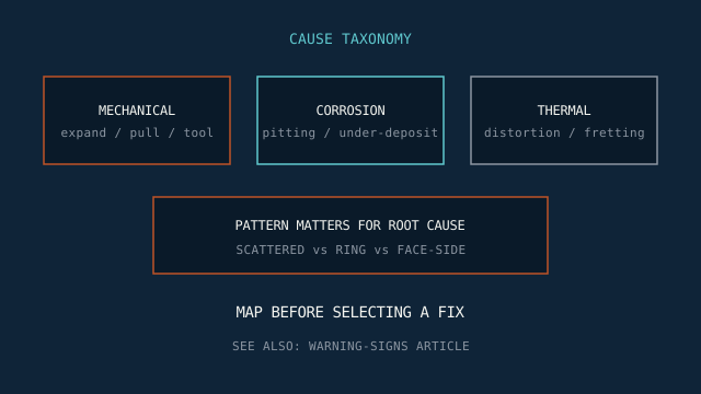
Photograph both faces, record hole IDs against the layout, and note whether damage clusters at the periphery, along a pass lane, or at random. Pattern interpretation overlaps the warning-signs article; hole-level metrology is what follows.
Mechanical: aggressive tube extraction, improper expander settings, foreign objects in the bore, or drilling/reaming errors on new sheets before release. Corrosion: process-side attack, galvanic couples, and deposit cells that deepen pits at the bore wall. Thermal / fretting: differential expansion, vibration, and gasket/baffle interaction that ovalises or work-hardens the entrance.
Root cause matters because a cosmetic blend will not stop chloride pitting, and a sleeve will not fix a calculation that already had marginal ligament. Materials context for aggressive media sits in material selection and service articles such as desalination replacement cycles — without turning this piece into a materials essay.
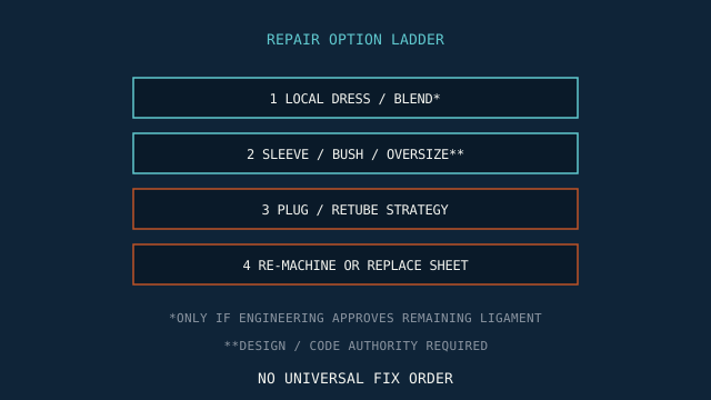
Common classes of response — each requires procedures, materials, and acceptance criteria approved for the equipment:
Welding repairs on tube sheets are procedure-controlled events (WPS/PQR, preheat, NDT where specified) — not ad-hoc bead placement. Joint philosophy for new work is covered in expanded vs welded joints; repair welding is a separate engineering package.
A single damaged hole rarely stands alone in structural terms. Enlarging one bore reduces ligament to its neighbours; chaining oversize repairs across a row can create a soft band. Before approving oversize or bush strategies, mark the affected holes on the pitch layout and recalculate or have the designer confirm remaining efficiency. Educational background on ligament and strength sits in how tube sheet thickness is determined; the repair calculation itself is an engineering deliverable, not a blog formula.
Peripheral holes next to the gasket groove or untubed partition lanes have different constraints than interior pattern holes. Damage at a partition boundary may implicate groove geometry and sealing, not only tube joint fit — bring feature inspection into the same work pack as bore repair.
Re-machining is a candidate when:
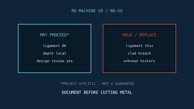
Re-machining is usually not appropriate when ligaments are already marginal, cracking is present, corrosion mechanism is active and uncontrolled, history/traceability is unknown, or the only “fix” would violate the Code package. In those cases, replacement or a broader retube/rebuild plan is the engineering conversation — not a shop improvisation.
Clad tube sheets add failure modes: clad disbond at the bore, clad thinning below minimum, and iron contamination on the process face after carbon-steel tooling. A repair that looks fine in base metal can leave the clad under-thickness. Any remachine plan on clad equipment must state remaining clad thickness criteria and whether local clad restoration is in scope — topics also touched in clad vs solid.
Explosive-clad or roll-bonded constructions may have different NDT histories; obtain prior data sheets before cutting. Titanium or high-nickel clad faces need procedures compatible with those alloys — do not assume carbon-steel blend practices transfer.
Strength-welded tube joints that are cracked at the fillet may look like “hole damage” but are joint damage. Separate the work packs: joint repair procedures versus bore geometry restoration. Mixing them without WPS control is a common outage error.
“Where specified” matters: not every damaged sheet requires every NDT method. Inventing a full NDT suite without a plan wastes outage time; skipping a required hold point creates compliance risk. New-build ITP thinking in the inspection article still applies as a documentation discipline.
Replacement becomes attractive when:
A replacement RFQ should include current design conditions, not only a rubbing of the old sheet. Materials may upgrade after chemistry review — desalination and seawater lessons in desalination cycles and marine-grade stainless show why copying the old grade can be a mistake. Still, upgrades need design authority.
Record hole IDs, measured values, photos, repair procedure references, welder/operator IDs where welding applies, and acceptance results. Update as-built drawings if geometry changed. Procurement of a replacement sheet — if chosen — should use a clean revision package via manufacturer RFQ path, not a verbal “same as old.”
Sometimes — when remaining ligament, clad condition and an approved repair or redesign drawing allow it. Re-machining is not always possible and is never a guarantee.
No. Blending is only a candidate when engineered limits for diameter, finish and ligament still hold after metal removal.
No. Tube sheets are pressure-boundary components. DIY or undocumented repairs can create unsafe conditions and compliance failures.
When damage is widespread, ligaments are marginal, clad is breached beyond scope, cracking is present, or repair risk exceeds replacement — as determined by the responsible engineer.
Plugs remove a hole from service within allowed plugging limits; they do not stop an active corrosion mechanism elsewhere.
No. New-build ITPs accept a manufactured sheet; in-service damage needs a repair plan tied to as-found condition.
Send measurements, photos and the governing drawing revision before any repair machining is planned.
Send an Enquiry →