NPRO Journal · TESTING
Tube Sheet Inspection
& Testing
A specification-driven release sequence — from material identity and dimensions to NDT where specified and final documentation.
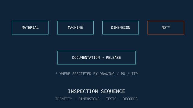
A specification-driven release sequence — from material identity and dimensions to NDT where specified and final documentation.
Tube sheet inspection and testing is how a fabricator proves that material, machining, drilling, and documentation match the approved drawing, purchase order, and Inspection and Test Plan (ITP) before release to tube insertion or field assembly. A drilled pattern that looks correct on the shop floor can still fail acceptance if mill certificates are not linked to the blank, if dimensional checks skip partition boundaries, or if required NDT was never called out on the order. Buyers who treat inspection as a final checkbox rather than a sequenced QA programme inherit rework, witness delays, and disputes at hydro or commissioning.
This guide explains the practical QA sequence for heat exchanger tube sheets: what to verify at each hold point, which checks are drawing-driven versus shop-standard, and how PMI and ultrasonic testing fit only where the specification requires them. It complements CNC tube sheet drilling process detail and the feature-focused article on tube sheet machining features. For supplier context and export documentation norms, see tube sheet manufacturer in India and the buyers guide. For definitions and buying context first, start with what is a tube sheet.
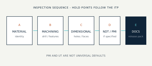
A coherent inspection programme follows the same order as production. Skipping ahead — for example, releasing a plate for drilling before material identity is confirmed — creates non-conformance that is expensive to unwind after hundreds of holes are cut.
Hold points should be agreed before production starts. Client or third-party witness at first-article holes or at final dimensional sign-off is common on EPC jobs; the ITP names who witnesses what and when.
Inspection begins with the blank, not the drill bit. The mill test certificate (MTC) or EN 10204 certificate must match the grade, product form, and heat or lot marked on the plate or forging. For stainless, duplex, nickel alloys, and titanium tube sheets, traceability errors are among the most serious non-conformances because they affect corrosion allowance, weld compatibility, and code compliance.
Practical checks at material receipt include:
Traceability must survive machining. Shops that split a plate or remanufacture from offcuts need a documented link so the finished tube sheet MTC still refers to the correct heat. Where the specification calls for PMI at receipt or before machining, that is a separate hold point — not a substitute for reading the MTC, but a verification layer where the ITP requires it.
Manufacturing hold points catch problems while scrap cost is still manageable. Typical pre-drilling holds include visual review of laminations or surface defects, confirmation of thickness after initial facing, and verification that datums used for CNC setup match the drawing.
On forged or heavy plate jobs, ultrasonic examination of the raw material may be specified on the PO for volumetric screening — again, only where called out, not as an automatic step for every disc. Clad plates may require bond inspection at defined stages; the drawing or cladding specification names the method and acceptance criteria.
Engineering review of manufacturability belongs upstream of these holds. Drawings with conflicting groove depths, impossible ligaments, or missing partition notes should be resolved before the first chip falls. Patterns that match governing standards on paper but conflict with the hole table are a frequent source of mid-job stops.
Dimensional inspection is the core acceptance activity for most tube sheet orders. What is measured depends on the drawing; there is no single universal checklist that fits every exchanger.
Common dimensional items include:
Measurement method should match the tolerance band. General micrometers and calipers suit many diameter checks; CMM or probing may be required for tight positional tolerances on large diameters. Record actual values, not pass/fail ticks alone, when the client specification asks for inspection reports.
TEMA-oriented projects often reference class-appropriate practice for tube hole tolerances and ligament rules; use the project drawing as primary and TEMA tolerance resources as supporting context, not as a override of client numbers.
Positive material identification (PMI) using XRF or OES verifies that the alloy at the point of test matches the specified grade. It is a valuable control for mixed-stock shops and for projects that mandate verification beyond certificate review.
PMI is not required on every tube sheet by default. It applies when the drawing, purchase order, client specification, or ITP explicitly requires it — for example at material receipt, after machining exposes fresh surface, or on final product sampling. Some owners require PMI on exotic grades or on every heat delivered to site; others accept MTC review alone for standard stainless plate.
When PMI is specified:
PMI confirms chemistry at the test spot; it does not replace dimensional inspection, does not detect internal defects, and does not prove heat treatment condition. Treat it as one line item in the ITP, not as shorthand for full quality assurance.
Ultrasonic testing (UT), radiography (RT), penetrant testing (PT), magnetic particle testing (MT), and other NDT methods each answer different questions. On tube sheets, UT may appear for forging or plate volumetric examination, clad bond inspection, or flaw detection in critical zones — always per the applicable code, drawing note, or PO clause.
UT is not automatic for every drilled tube sheet. A standard process exchanger with solid stainless plate and no NDT note on the drawing does not implicitly require bond UT or hole-wall scanning unless the purchaser adds that scope. Conversely, clad tube sheets for severe service often carry explicit bond UT requirements that must be scheduled before or after machining so access and acceptance criteria are achievable.
When NDT is specified:
Drilling hundreds of holes changes the plate acoustically and geometrically; UT plans must account for machined surfaces and edge distance. For clad work, coordinate NDT hold points with machining features so grooves and faces do not remove the last zone needed for bond examination.
Tube sheet acceptance is not only hole metrology. Gasket seating faces, pass-partition grooves, serrations, and counterbores affect shell-side sealing, hydro test integrity, and tube-side pressure boundary behaviour. Visual inspection catches burrs, tear-out at hole exits, chatter on gasket lands, and clad discontinuity at machined steps.
Surface finish requirements belong on the drawing. A face specified for spiral-wound gasket seating needs different verification from a rough as-milled land. Where finish Ra or Rz limits are stated, agree measurement method and number of readings before production.
Cleaning verification is part of surface acceptance. Chips left in holes or grooves have caused tube insertion damage and false leak paths during pressure test. Confirm blow-out, brushing, or washing steps and record them when the ITP requires.
Post-delivery in-service inspection — looking for leak signs, corrosion, or joint failure — is a separate lifecycle topic. For field and turnaround context, see warning signs on tube sheet and joint condition.
Final release depends on a complete, coherent paper or electronic trail. Typical packages include:
Export and EPC projects often add packing lists, country-of-origin statements, and third-party inspection release notes. Align the pack early with the buyers guide and client vendor data requirements so missing indexes do not delay shipment after the plate is physically ready.
Documentation without dimensional truth is hollow. Conversely, a perfect part with mismatched heat numbers on the certificate will fail client receipt inspection. Treat the pack as part of the deliverable, not as admin afterthought.
Inspection scope should be frozen at enquiry, not invented at final dispatch. The RFQ and ITP together answer: what is measured, how much sampling applies, which NDT methods are mandatory, and who witnesses hold points.
Fields that reduce ambiguity:
Vague language such as “full QC” or “as per standard practice” produces incompatible quotes. One vendor assumes MTC only; another includes bond UT and 100% PMI. Mirror the project ITP in the purchase specification and reference standards by edition, not by name alone.
Repeated failures in tube sheet acceptance often trace to specification gaps rather than machine capability.
Strong inspection planning treats the tube sheet as a pressure-boundary component: material identity, geometry, specified NDT, and traceable records must align before tubes go in. Work with a manufacturer who quotes inspection scope explicitly — as outlined for domestic and export buyers on tube sheet manufacturing in India — and who can execute CNC drilling and feature machining under the same QA sequence.
Follow a specification-driven sequence: material identity, manufacturing hold points, dimensional checks against the drawing, then any PMI or NDT methods required by the purchase order or inspection plan, then documentation review before release.
Envelope or OD, thickness and flatness where specified, hole diameter, pitch and position, layout and untubed zones, and feature geometry such as grooves and gasket faces — to the drawing tolerances.
No. Perform PMI where specified by the drawing, purchase order, governing specification or inspection plan.
No. Ultrasonic testing is used when the project specification chain requires it. Scope it explicitly.
Commonly mill certificates and dimensional records, plus any NDT or PMI reports and witness certificates required by the purchase order — not a universal fixed pack.
By measuring pitch and position on sample or critical holes, and fuller patterns when specified, especially near periphery and partition boundaries, against the released hole map.
Identity of the part and revision, measuring references, results versus tolerance, traceability to heat or lot, and signatures or hold-point releases required by the inspection plan.
Include inspection scope and documentation expectations with the released drawing so quotes match the ITP.
Send an Enquiry →